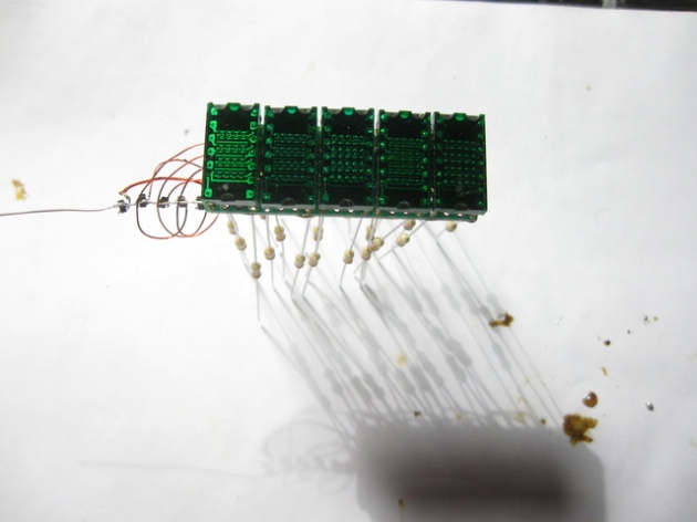
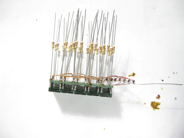
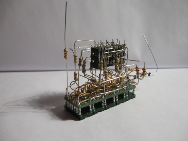
Some time ago I got several HDSP-2011 displays. They look cool: ceramic, gold-plated pins and traces, sapphire glass… Driving them is not exactly straight-forward. Pixel data has to be shifted in, one column at a time, and then column pin has to be connected to approximately +3V supply. Columns need multiplexing, which means sending serial data (almost) continuously while displaying. I choose to use one of Atmega8 chips I have in my junk.
First approach was purely software based: bit-banging Data In and Clock inputs of HDSP-2011. Then I connected two displays in a daisy-chain (Data Out of the first display to Data In of the second one, and common Clock signal). I was thinking that maybe USART could be used to send the data, offloading the microcontroller. It could, but only when using newer Atmega chips (Atmega 48/88/168 has USART SPI Master mode). Wait a minute, why not use SPI interface instead? It’s confirmed working. So I used (and modified) Mike’s code.
Schematic was never drawn (the whole thing was re-soldered a few times). The connections are:
| Atmega8 | HDSP-2011 |
| MOSI (PB3) | Data In (pin 12) |
| SCK (PB5) | Clock (pin 10) |
Column pins are connected to emiter followers (FMMT493TA), driven by PD3 to PD7 Atmega pins (through 330Ω resistors). 5V supply is connected through two silicon diodes, effectively decreasing the voltage to required 2.8 ÷ 3.1V (diodes to 3.6V, transistor to 2.9V). Atmega is clocked at 16MHz, using quartz oscillator (not required, I needed a stable clock for other purpose).
And that’s it. The rest is in the software (warning: it’s quite messy):
#include <avr/io.h>
#include <avr/sleep.h>
#include <avr/pgmspace.h>
#include <avr/interrupt.h>

#define SHIFT_REGISTER DDRB
#define SHIFT_PORT PORTB
#define DATA (1<<PB3)           //MOSI (SI)
#define LATCH (1<<PB2)          //SS   (RCK)
#define CLOCK (1<<PB5)          //SCK  (SCK)

#define COLUMN_REGISTER DDRD
#define COLUMN_PORT PORTD
#define COLUMN0 (1<<PD3)
#define COLUMN1 (1<<PD4)
#define COLUMN2 (1<<PD5)
#define COLUMN3 (1<<PD6)
#define COLUMN4 (1<<PD7)

volatile uint8_t bitplane = 0, column = 0, counter = 0;

volatile uint8_t framebuffer[] = {
        0x00, 0x00, 0x00, 0x00, 0x00, 0x00, 0x00,
        0x00, 0x00, 0x00, 0x00, 0x00, 0x00, 0x00,
        0x00, 0x00, 0x00, 0x00, 0x00, 0x00, 0x00,
        0x00, 0x00, 0x00, 0x00, 0x00, 0x00, 0x00,
        0x00, 0x00, 0x00, 0x00, 0x00, 0x00, 0x00,

        0x00, 0x00, 0x00, 0x00, 0x00, 0x00, 0x00,
        0x00, 0x00, 0x00, 0x00, 0x00, 0x00, 0x00,
        0x00, 0x00, 0x00, 0x00, 0x00, 0x00, 0x00,
        0x00, 0x00, 0x00, 0x00, 0x00, 0x00, 0x00,
        0x00, 0x00, 0x00, 0x00, 0x00, 0x00, 0x00

};

void hdsp2011_put_pixel(int8_t x, int8_t y, int8_t color) {
        int8_t moddiv5 [] = {
                0x00, 0x10, 0x20, 0x30, 0x40,
                0x01, 0x11, 0x21, 0x31, 0x41,
                0x02, 0x12, 0x22, 0x32, 0x42,
                0x03, 0x13, 0x23, 0x33, 0x43,
                0x04, 0x14, 0x24, 0x34, 0x44,
                0x05, 0x15, 0x25, 0x35, 0x45,
                0x06, 0x16, 0x26, 0x36, 0x46,
                0x07, 0x17, 0x27, 0x37, 0x47
        };

        //int16_t pixnum = (x/5)*7 + (x%5)*56 + y;
        // Is the following faster than the line above?
        int16_t pixnum = (moddiv5[x] & 0x0F)*7 + (moddiv5[x]>>4)*56 + y;

        int16_t addr = pixnum >> 3;
        int8_t bit = pixnum & 0x07;
        // Clear the pixel
        framebuffer[addr] &= ~(1 << bit);
        framebuffer[addr+35] &= ~(1 << bit);
        // Draw new pixel
        if (color & 1) framebuffer[addr] |= (1 << bit);
        if (color & 2) framebuffer[addr+35] |= (1 << bit);

}
        volatile int8_t x = 0, y = 0, dx = 1, dy = 1, color = 2;
        volatile uint8_t bnc_cntr = 0;

/***********************
 * PROGRAM STARTS HERE *
 ***********************/

int main(void) {
  // Setup IO
  SHIFT_REGISTER |= (DATA | LATCH | CLOCK);     // Set control pins as outputs
  SHIFT_PORT &= ~(DATA | LATCH | CLOCK);                // Set control pins low

  // Setup SPI
  // SPI enable, master, rising SCK trailing edge
  // *** upside-down
  //SPCR = (1<<SPE) | (1<<MSTR) | (1<<CPOL) | (1<<DORD);
  // *** normal
  SPCR = (1<<SPE) | (1<<MSTR) | (1<<CPOL);

  // Setup column port
  // Columns at bits 0 to 4 as outputs
  COLUMN_REGISTER = COLUMN0 | COLUMN1 | COLUMN2 | COLUMN3 | COLUMN4;
  // Drive columns blank
  COLUMN_PORT &= ~(COLUMN0 | COLUMN1 | COLUMN2 | COLUMN3 | COLUMN4);

  // Pull LATCH low (Important: this is necessary to start the SPI transfer!)
  SHIFT_PORT &= ~LATCH;

  // Timer prescaler:
  // 001 1
  // 010 /8
  // 011 /64
  // 100 /256
  // 101 /1024
  // 110 ext. rising edge
  // 111 ext. falling edge
  TCCR0 |= (1<<CS01);// | (1<<CS00);
  //TCCR0 |= (1<<CS02);// | (1<<CS00);
  // Enable timer overflow interrupt
  TIMSK |= (1<<TOIE0);
  // Initialize timer
  TCNT0 = 0;

  // Enable interrupts
  sei();

  while(1) {
          sleep_enable();
          //sei();
          sleep_cpu();
          sleep_disable();
  }
        return 0;
}

void frame_complete() {
        // Bouncing Pixel!
        if ((counter == 10)) {
                hdsp2011_put_pixel(x, y, (color-2) % 4);
                x += dx;
                y += dy;

                if (x < 0) {
                        x = 0;
                        //goto out_x;   // Use goto if you *need* to save a few bytes of flash
                        dx = -dx;
                        bnc_cntr++;
                }
                if(x > 39) {
                        x = 39;
//out_x:
                        dx = -dx;
                        bnc_cntr++;
                }
                if (y < 0) {
                        y = 0;
                        //goto out_y;
                        dy = -dy;
                        bnc_cntr++;
                }
                if (y > 6) {
                        y = 6;
//out_y:
                        dy = -dy;
                        bnc_cntr++;
                }
                hdsp2011_put_pixel(x, y, 3);
                counter = 0;
                if (bnc_cntr > 64) {
                        color++;
                        bnc_cntr = 0;
                }
        }
}

ISR(TIMER0_OVF_vect) {
        int8_t i;
        // Blank the display
        COLUMN_PORT &= ~(COLUMN0 | COLUMN1 | COLUMN2 | COLUMN3 | COLUMN4);

        for(i=6; i>=0; i--) {
                // There was simpler way, it looks better (on the display) this way though:
                if (bitplane == 0) {
                        SPDR = framebuffer[column*7 + i];
                } else {
                        if (bitplane < 4) {
                                SPDR = framebuffer[35 + column*7 + i];
                        } else {
                                SPDR = (framebuffer[column*7 + i] & framebuffer[35 + column*7 + i]);
                        }
                }

                /*
                switch (bitplane) {
                        case 0:
                                SPDR = framebuffer[column*7 + i];
                                break;
                        case 1:
                        case 2:
                        case 3:
                                SPDR = framebuffer[35+column*7 + i];
                                break;
                        default:
                                SPDR = (framebuffer[column*7 + i] & framebuffer[35+column*7 + i]);
                }
                */
                while(!(SPSR & (1<<SPIF)));
        }
        // *** upside-down
        //COLUMN_PORT |= (1 << (7-column));     // Select proper column (un-blank)
        // *** normal
        COLUMN_PORT |= (8 << column);   // Select proper column (un-blank)
        bitplane++;
        if (bitplane > 6) {
                bitplane = 0;
                column++;
        }

        // Once every screen refresh:
        if (column == 5) {
                counter++;
                frame_complete(); // This could run in a main loop, keeping ISR short, but...
                column = 0;
        }
}
Quick explanation: ISR routine sends “framebuffer” data to the HDSP-2011s using SPI. It also allows 3 levels of brightness, independently for each pixel. Organisation is bitplane-wise (with hard-coded offset of 35). This allows displaying 5×7 fonts while using little CPU cycles (just a few OR operations). The plan was (is!) to make anti-aliased fonts, or using brightness levels as phosphor display emulation.


